Building a stackable motor driver shield for Arduino
Posted by Nick Johnson | Filed under busdriver-shield, i2c, avr, arduino
Hi, Hack a Day readers! If you're just looking for the source and schematics, they're here. Otherwise, read on!
Recently I've been working with embedded electronics a bit for a project I'm working on, using an Arduino. For the project, I need to control a number of low-power DC motors, and while there are plenty of solutions out there for driving one or two (or even three) like this, none of them let you drive as many motors as I need, and none of them are stackable, as they all require exclusive use of some IO lines. I could get several standalone driver boards like these, but I didn't much like the prospect of the ratsnest of wiring that would ensue. So, I decided to develop my own.
Before I go on, a brief aside about motor drivers. Motors can require a lot of power, so powering them directly from a microcontroller's IO pins is not practical. The obvious solution is to use a simple transistor, but in many cases, including mine, it's necessary to be able to drive the motor both forward and backwards, which isn't possible using a simple transistor setup. The solution is something called an H-Bridge, which is capable of driving a motor both forwards and backwards, and can be controlled over standard 5v logic pins. An H-Bridge is at the core of all the motor driver boards you're likely to see.
Designing and fabricating a custom circuit board is a new experience for me, but it's turned out to be pretty straightforward and surprisingly easy. The most commonly used tool for PCB design is Cadsoft's Eagle, and they conveniently provide a free version which, while limited to 100 x 80mm board area and two layers is ample for designing small boards like Arduino shields. For fabrication, Seeedstudio provide a ridiculously cheap service, coming in at $25 US for 10 arduino-sized boards.
Having decided I wanted to design my own shield, the next question is how to build it. Since I need to make a stackable shield, I can't use dedicated IO lines, so a serial bus of some sort is necessary, and I2C is the obvious choice. I2C is a straightforward serial protocol that supports connecting hundreds of devices on the same bus, and it's widely supported by microcontrollers and other hardware. Arduino provides a library called Wire for communicating over the I2C bus.
A simple solution would be to use an I2C bus expander. These are devices that provide a set of extra IO lines that can be read and written over I2C, and they're cheap and easy to use. Grab one, hook it up to the H-Bridge, and you're ready to go. IO expanders - at least the affordable ones - are a bit limited, though. Most notably, they don't support PWM output, which means there's no speed control - the motor is either stopped, or going full bore.
As you might guess, however, there is a better solution. Atmel has a range of low-powered AVR microcontrollers called ATTiny, and one of them, the ATTiny2313, is perfectly suited to my needs. For only about $0.80 more than the I2C expander, it's a shoo-in. What's more, it has plenty of inputs and outputs, enabling some additional features that wouldn't have been possible with the I/O expander.
Having decided on the controller, I set to work in Eagle, eventually producing this:
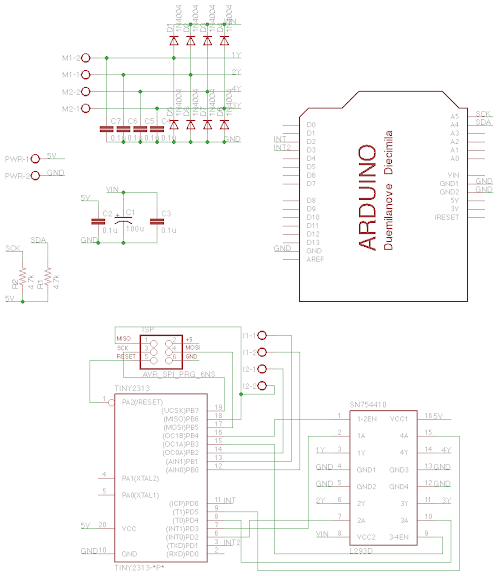
Although it looks complex at first glance, it's actually fairly straightforward. Outputs from the ATTiny connect to the H-Bridge, with 1 pin to enable each of the 2 motors, and 4 pins providing directional control for those motors. The enable pins support hardware PWM, making it easy to do speed control. Two more pins connect to the host Arduino for I2C communications, and an ISP header is included so the microcontroller can be reprogrammed with new firmware after being soldered onto the board. Screw terminals provide an easy way to connect the motors to the shield.
Besides the microcontroller and the H-Bridge, the only other components on the board are a few diodes and capacitors. The motor drive includes internal kick-back diodes, to prevent voltage spikes when the motor is turned off, but there seems to be some debate about whether the ones in this H-Bridge are sufficient for the job, or merely intended to be used to protect against electrostatic discharge. I added external ones for safety's sake. The capacitors are there to provide decoupling - smoothing out the power supply from the short-term spikes and dips driving motors causes. I learned a lot about decoupling in the process of designing this circuit. The microcontroller has an internal clock circuit, so no external crystal oscillator is required, further simplifying things.
You may have noticed there's also four wires leading from the ATTiny to another set of screw terminals. I mentioned earlier that the presence of spare inputs on the microcontroller made it possible to add some extra features, and this is that. The inputs are intended to be connected to limit switches or a Quadrature Encoder, and make it possible for the motor shield to do some of the work that would normally be up to the host Arduino, such as counting revolutions, or stopping the motor when it hits a limit switch. Two more inputs are used to signal events like this back to the Arduino as interrupts. Although they connect to dedicated input lines, their use is optional, and furthermore, they can be shared, so multiple shields can use the same interrupt line.
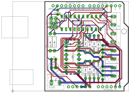
After some basic breadboard tests to verify my design wasn't totally crazy, I set to designing the layout of the circuit board. Some further work in Eagle's layout designer produced this, which I sent off to Seeed for fabrication:
While I waited for Seeed to build the PCBs and mail them to me, I worked on the firmware. This proved to be an interesting challenge too, since I've never worked with raw AVR code before - the Tiny2313 has only 2k of program space and 128 bytes(!) of RAM, so the Arduino bootloader and environment is right out.
The main hurdle to overcome is making the microcontroller act as an I2C slave. While more sophisticated MCUs like the ATMega range have complete built-in I2C support, the ATTiny range have only a "Universal Serial Interface", which provides circuitry to buffer a single byte of serial data, and a "start condition detector", which detects the start of an I2C message. Libraries built on this proved difficult to find, however, and many of them are of very low quality, and uncertain licensing status. Eventually I found the excellent usi-i2c-slave library, however, which in addition to being well written, compact, and robust, uses a register model for I2C communication - exactly what I needed.
With the communication in hand, writing the rest of the firmware was fairly straightforward. I soon had a fairly capable motor driver firmware written, and just had to wait for the PCBs to arrive. Eventually, they did:
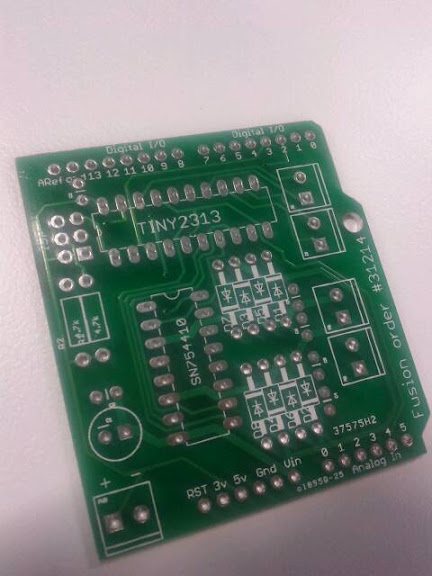
The quality of the PCB fabrication was excellent, especially considering the extremely low price I paid. Shortly thereafter, I had a finished shield put together:
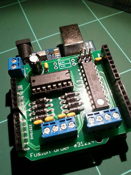
The end result is very satisfying - the shields work perfectly. I honestly expected to make a stupid mistake my first time designing a PCB, but I appear to have avoided that, though there's a few things I'd change in a revision two - which I'll talk about below.
Here's a final feature list:
- Drive two DC motors at 6-12 volts, with up to 1A current draw each.
- Full independent, proportional PWM speed control over both motors.
- Control and feedback over the I2C serial protocol.
- I2C address is configurable to any valid address. Address and other configuration values can be saved to EEPROM for persistence between reboots.
- Entirely stackable - pile as many as you need on top of each other to drive many motors, limited only by the current you can supply and the length of the I2C bus.
- Two inputs per motor allow the shield to handle limit switches and quadrature encoders without involvement from the host processor.
- Two interrupt lines can be optionally used to signal events such as limit switch triggering back to the host processor.
Despite the lengthy feature list - unique as far as I can tell - the whole project cost very little. In quantities of 10, for all the parts, the project came to less than $15 per shield - only $10 if you exclude the cost of the headers and screw terminals. In quantities of 50 or more, the cost would be under $10, again omitting the screw terminals and headers.
So, what would I change next time? There's a few things I would revise in an ideal world:
- Screw terminals are convenient, but I think I'd use right-angle header pins in a revised design. With a little effort terminating the wires, it becomes possible to connect and disconnect the motors without having to unstack and restack the shields.
- In addition to the above, I'd collect the motor pins, the two input pins, and a VCC and ground line into a single 6-pin header for each motor. That way, a single ribbon cable can be used to connect up a motor and its sensors to the shield.
- The pins for the I2C bus are on the opposite side of the shield to the microcontroller, something I didn't realise until most of the way through the design. Ideally, I'd reorganize the layout to put the micro much closer to those pins. In practical use this probably won't matter, but if you have a lot of devices on the bus, shorter wire runs are better.
- There's a few places I'd like to tweak the layout of the copper tracks to shorten traces and neaten things up.
If you'd like to build your own, or use what I've produced for whatever else you have in mind, the whole project is open source, and available here on Github. If you do something interesting with it, I'd love to hear about it!
If you're just interested in one or several of the shields, let me know in the comments. If there's enough interest, I may get a larger batch of v2 shields (with the improvements I listed above, and any other useful ones people suggest) made, and sell the kits - probably for around $15 each.
Edit: Since there seems to be some interest in a v2 version of the shields, I've put up a preorder form to see if there's a critical mass of people to place the PCB order. If you're interested, fill the form out here.
Previous Post Next Post